Understanding the Modbus server address Map
The Modbus server address map documents the registers that an external Modbus client can use to read data from, or write supported values to, an EPM Data Management device. The address map details the EPM channel or function associated with each register, the parameter exposed, the data format and the access level.
Understanding the exported address map
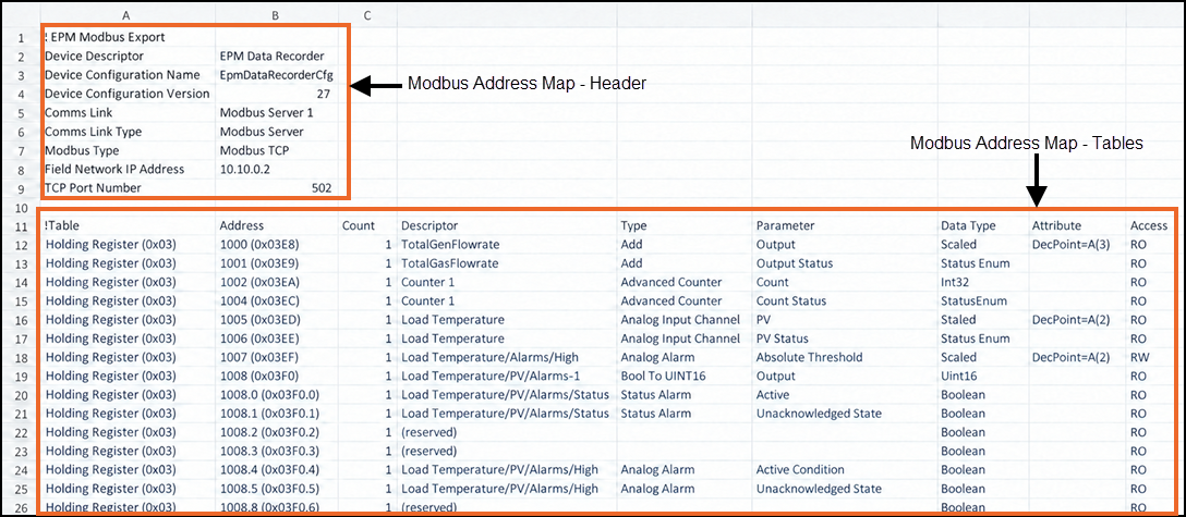
The exported address map is a delimited text file. Open the file in your preferred spreadsheet application or text viewer:
-
Lines that begin with an exclamation mark (!) contain comments or section titles.
-
The file contains a header section and an address map section.
-
The header section contains the application and communication-link settings.
-
The address map section lists the registers and their properties.
Understanding the header section
The header section identifies the application and the communications link used to generate the address map:
-
The application to which the address map applies.
-
The Comms Link settings.
| Header Entry | Value Source | Description |
|---|---|---|
| Device Descriptor | Settings and Users - Settings - General Settings - Device Descriptor | Identifies the EPM device, for example, EPM Data Recorder |
| Device Configuration Name | Settings and Users - Settings - General Settings - Configuration Name | Identifies the device configuration, for example, EpmDataRecorderCfg |
| Device Configuration Version | About - System Information | Identifies the configuration version used to generate the map, for example, 25 |
| Comms Link | Device I/O - Comms Link - Descriptor | Identifies the communication link, for example, Modbus Server 1 |
| Comms Link Type | Device I/O - Comms Link - Type | Identifies the type of communication link, for example, Modbus Server |
| Modbus Type | Device I/O - Comms Link - Modbus type | Identifies the Modbus protocol, for example, Modbus TCP |
| Field Network IP Address | Settings - Networks - Field Network | The IP address that the Modbus client uses to connect to the server, for example, 10.10.0.2 |
| TCP Port Number | Device I/O - Comms Link - Port Number | The TCP port used by the Modbus server, for example, 502 |
Understanding the address map table
The address map table contains one row for each data item. A data item is a Descriptor and Parameter pair:
-
The Modbus addresses.
-
The parameter mapping, Descriptor, Data Type, and related information.
| Column | Description |
|---|---|
| Table | Identifies the Modbus table type, for example, Holding Register and the read function code, for example, 0x03. Where parameters are writable the appropriate write function code matching the read function code can be used. See Modbus Server supported function codes. |
| Address | The Modbus address. Each table type (e.g. Holding Register) has an independent address range from 0 to 65535. Where a data item (<Descriptor>/<Parameter> pair) requires more than one address, this is the start address of the data. |
| Count | Shows the number of Modbus addresses used by the data item (<Descriptor>/<Parameter> pair). For example, a numeric value such as Analogue Input/PV might use 1 address (register) for Data Type Scaled, or 2 addresses (registers) for Data Type Float32. String data typically uses the highest counts, for example, a batch field of Data Type Packed ASCII might use 32 addresses (registers) |
| Descriptor | Identifies the EPM channel, alarm, packed alarm register, batch etc. associated with the address. |
| Type |
Note - The Type is separate and distinct from the Data Type described below.
Identifies the channel type or function of the Descriptor associated with the address. In many case such as I/O, Alarms, Maths, Timers, Totalizers, Counters, Application functions and Batch, the Type matches that shown on the configuration page. For I/O, this is the title shown with the configuration settings, for example:
For Maths, Timers etc. this is the Type shown on the configuration page, for example:
For Batch, this is the ‘batch configuration‘ name, for example:
|
| Parameter | Identifies the specific value or status exposed by the register, such as Output, PV, Total, Active, or Absolute Threshold. |
| Data Type | Identifies how the value is encoded. Examples include Scaled (1 register), Float32 (2 registers), StatusEnum (1 register), UInt16 (1 register), Int32 (2 register), Boolean and PackedASCII (1 to ‘n’ registers depending upon string length). |
| Attribute | Provides additional information about the data format. For example, DecPoint=A(2) indicates that the scaled value uses two decimal places. |
| Access | Shows whether the Modbus client can read or write the register. RO means read-only and RW means read/write. |



Understanding numeric values
The Modbus address map exposes numeric values as either Float32 or Scaled. These Data Types use different register formats. Always consider the Table, Address, Count, Data Type, Attribute, and Access values shown in the current exported map when reading or writing a value.
Float32 values
A Float32 value uses the IEEE 754 32-bit single-precision floating-point format. The value is transferred as two consecutive 16-bit registers:
-
The address in the map identifies the first register.
-
When writing a Float32 value, both registers must be written in the same Modbus message.
Example: A Float32 value of 1.0 uses the 32-bit pattern 0x3F800000.
The two registers contain 16256 (0x3F80) and 0 (0x0000).
Scaled values
A Scaled value uses one signed 16-bit Modbus register. The register value ranges from –32768 to +32767.
The DecPoint attribute identifies the number of decimal places. The EPM value is converted as follows:
-
From EPM to Modbus - Modbus register value = EPM value × 10^n
-
From Modbus to EPM - EPM value = Modbus register value ÷ 10^n
EPM value DecPoint = n Register value Conversion 12.3478 2 1234 (0x04D2) 12.3478 × 10^2, truncated −875 0 −875 (0xFC95) −875 × 10^0 0.0345706 4 345 (0x0159) 0.0345706 × 10^4, truncated
| Register value | DecPoint = n | EPM value | Conversion |
|---|---|---|---|
| 1234 (0x04D2) | 2 | 12.34 | 1234 ÷ 10^2 |
| −875 (0xFC95) | 0 | −875 | −875 ÷ 10^0 |
| 345 (0x0159) | 4 | 0.0345 | 345 ÷ 10^4 |
Status Enum
A StatusEnum value is transferred as one Modbus register. The Modbus values correspond to EPM status values as follows:
| Modbus value | Meaning | EPM status value |
|---|---|---|
| 0 | Good PV | Calibrating |
| 1 | Channel Off | Off |
| 2 | Over Range | Input Over Range |
| 3 | Under Range | Input Under Range |
| 4 | Hardware Error | I/O Hardware |
| 5 | Ranging Error | Ranging |
| 6 | Overflow | Unused in EPM |
| 7 | Bad PV | Invalid, Configuration error, Calibration error, Sensor Break, Clipped, Uninitialized, or Not representable |
| 8 | No Data | No Data |
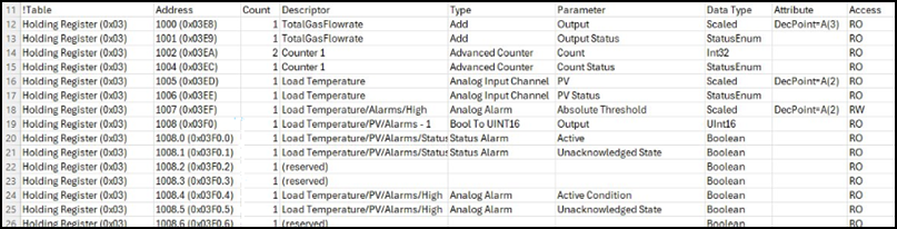
The status of each alarm is transferred as packed bits in a Modbus register. Each packed status register contains the status of up to four alarms:
-
If a channel has more than four alarms, the address map contains more than one packed alarm status register.
-
The address map identifies the packed register address and the bit used by each alarm.
-
Dot notation identifies a bit within a register. For example, 1008.0 identifies bit 0 of register 1008.
-
All dot entries refer to the same register; the dot notation documents the bit usage. Address 1008 (0x03F0) is the packed status register for the Load Temperature channel.
The following entries identify the bit allocation within that register:
| Alarm group | Bit positions | Bit use |
|---|---|---|
| Alarm 4 | 15 to 12 | R R U A |
| Alarm 3 | 11 to 8 | R R U A |
| Alarm 2 | 7 to 4 | R R U A |
| Alarm 1 | 3 to 0 | R R U A |
-
A - Active: 1 means the alarm is active; 0 means the alarm is inactive.
-
U - Unacknowledged: 1 means the alarm is unacknowledged; 0 means the alarm is acknowledged.
-
R - Reserved: the value is not used. Ignore it.
String values use the PackedASCII data type. PackedASCII stores two 8-bit ASCII characters in one 16-bit Modbus register:
-
The Count value reserves space for the string. The maximum string length is 2 × Count characters.
-
A string shorter than the reserved space uses the configured string terminator.
-
A string that is the same length as or longer than the reserved space uses the full allocated space and has no terminator.
| Attribute | Description |
|---|---|
| NullTerminated | Adds an ASCII NULL character (0x00) after the final character. |
| SpacePacked | Adds ASCII spaces (0x20) after the final character until the allocated field is full. |
Most EPM strings support Unicode characters from the Basic Multilingual Plane (BMP-0). When EPM transfers a string as PackedASCII, it converts non-printable ASCII characters to a hyphen (0x2D).
For example, the first register for the string “Test” contains 0x5465:
| Representation | Most Significant Byte | Least Significant Byte |
|---|---|---|
| Numeric Value (decimal) | 84 (0x54) | 101 (0x65) |
| ASCII Character | T | e |
Monitoring and controlling batches
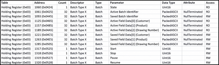
You can monitor a running batch and start a new batch through Modbus. The content of the address map depends on the batch configuration. The number of batch-field entries matches the number of fields configured for each batch:
Active and Saved batch data
EPM exposes two sets of batch data through Modbus: Saved data and Active data.
-
Saved Batch Identifier and Saved Field Data contain the values prepared for the next batch start.
-
Active Batch Identifier and Active Field Data contain the values for the batch that is currently executing.
-
Writing saved registers does not immediately update active registers.
-
When the batch accepts the Start command, the batch engine copies the saved data to the active data.
Batch state
| Value | State | Description |
|---|---|---|
| 0 | Empty | No batch is loaded. |
| 1 | Idle | A batch is available but is not running. |
| 2 | Running | A batch is running. |
| 3 | Held | Reserved for future use. A batch is held. |
| 4 | Pause | A batch is paused. |
| 5 | Stopped | A batch is stopped. |
| 6 | Aborted | A batch has been aborted. |
| 7 | Failed | A batch has failed. |
| 8 | Completed | A batch has completed. |
| 9 | Restarting | A batch is restarting. |
| 10 | Holding | Reserved for future use. A batch is transitioning to Held. |
| 11 | Pausing | A batch is transitioning to Paused. |
| 12 | Stopping | A batch is transitioning to Stopped. |
| 13 | Aborting | A batch is transitioning to Aborted. |
| 14 | Loading | A batch is loading. |
Batch commands
To issue a batch command, write 1 to the command register. The EPM Modbus Server automatically resets the register to 0. Monitor the State register to confirm the result.
| Command register | Command register Accepted when | State after success |
|---|---|---|
| Start | State = Idle. Write the saved field data and, if required, the saved batch identifier before issuing Start. | Running |
| Pause | State = Running. | Paused |
| Resume | State = Paused. | Running |
| Stop |
State = Running State = Paused. |
Idle The batch function is ready for a new batch to have batch fields written and the start command issued. |
Setting up and running a batch through Modbus
The following sequence assumes that a batch and a Modbus communications link are configured and running on the EPM device:
-
If the batch identifier is not generated automatically, write the identifier to the Saved Batch Identifier registers. See Configuring a Batch.
-
Write the required batch-field values to the Saved Field Data registers.
-
Confirm that the batch State is Idle and that batch identifier and all batch data is as required.
-
Write 1 to the start command register.
-
Confirm that state changes to Running. The batch engine copies the saved data to the active data.
-
To pause the batch, write 1 to the Pause command register. To resume it, write 1 to the Resume command register.
-
To stop the batch, write 1 to the Stop command register. The command is accepted only when State is Running or Paused. The batch returns to Idle.